The original design of the VTSSHD consisted of a BeagleBone Black with a custom expansion board. Due to a problem with one of our original sponsors, these boards were never manufactured. An alternate design was used (with similar functionality).
Current Electrical Design
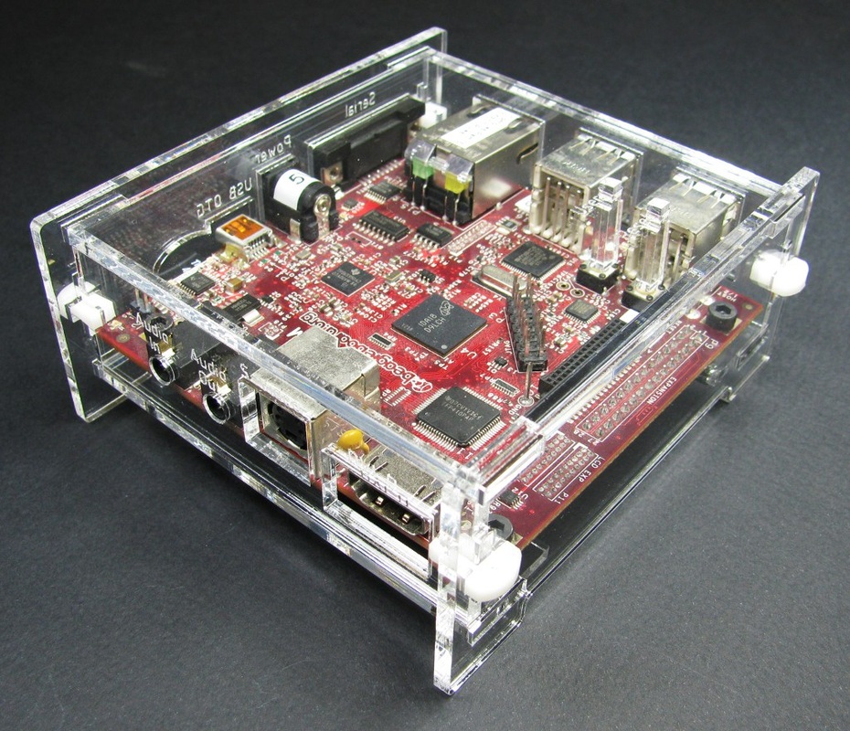
The Beagleboard-xM is utilized for this device as the embedded computer. It is responsible for doing majority of the processing and then sending the results to the piezo drivers. The BeagleBoard-xM has inbuilt audio in and audio out ports. We use the audio in port on the board to read in speech, either via an amplified microphone or just playing pre-recorded speech from a smartphone.
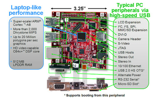
The image below shows some specifications of the BeagleBoard-xM, along with all its ports and capabilities. Most of the hardware features are not used for this project, such as the Camera Header, S-Video, and a few more.
The image below shows some specifications of the BeagleBoard-xM, along with all its ports and capabilities. Most of the hardware features are not used for this project, such as the Camera Header, S-Video, and a few more.
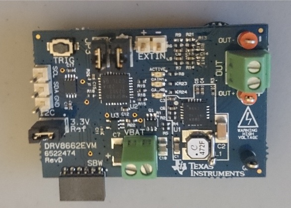
For piezoelectric elements actuators to generate vibrations strong enough to be felt on the user's skin, they need to be driven at high voltages (100-200Vpp). This can be done using Texas Instruments's DRV8662 chip. Conveniently, a DRV8662 evaluation module (DRV8662EVM) is available.
The evaluation module was slightly modified to accept a 1.8V PWM single-ended signal (instead of a 3.3V differential PWM or analog signal).
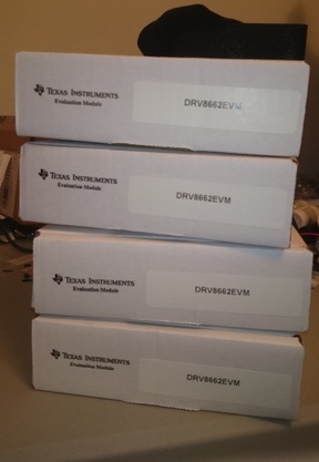
Texas Instruments generously donated two DRV8662EVMs.
The evaluation module was slightly modified to accept a 1.8V PWM single-ended signal (instead of a 3.3V differential PWM or analog signal).
Texas Instruments generously donated two DRV8662EVMs.
|
|
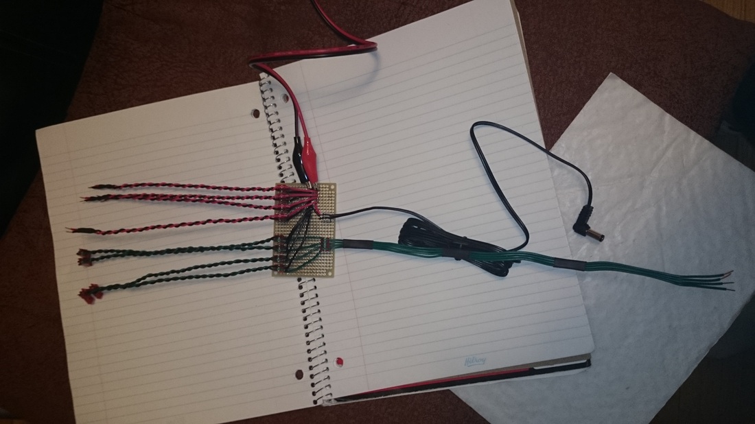
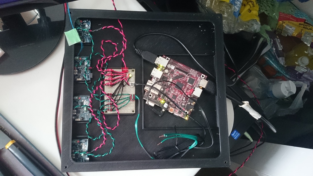
Using a perfboard, power and various signals are routed appropriately. This was made to ensure "electrical tidiness" and that we could perform various tests easily by connecting and disconnecting things easily.
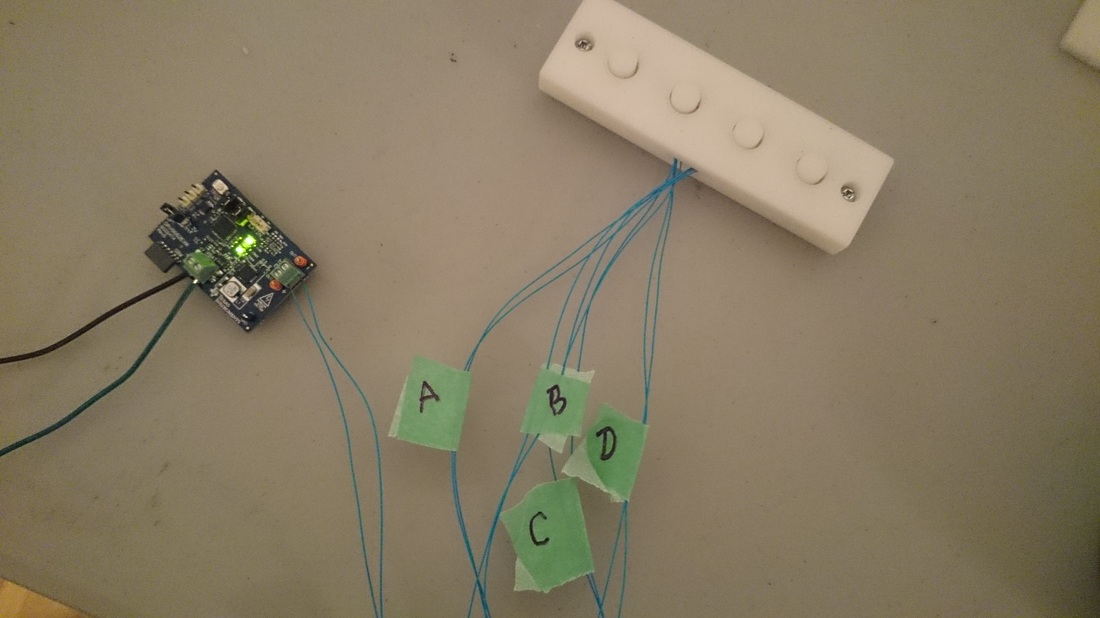
The barrel connector powers the BeagleBoard-xM. The twisted red and black wires power the DRV8662EVMs. The twisted green and black wires provide the DRV8662EVMs with a PWM signal. BeagleBoard-xM send the PWM signal through the four green wires on the right.
The barrel connector powers the BeagleBoard-xM. The twisted red and black wires power the DRV8662EVMs. The twisted green and black wires provide the DRV8662EVMs with a PWM signal. BeagleBoard-xM send the PWM signal through the four green wires on the right.
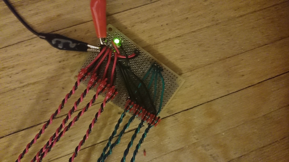
An LED was added to indicated that the system is powered.
All matching pairs of wires were twisted together. This helped with electrical tidiness.
The two alligator clip wires are connected to a bench DC power supply, configured at 5V.
All matching pairs of wires were twisted together. This helped with electrical tidiness.
The two alligator clip wires are connected to a bench DC power supply, configured at 5V.
Given the high cost of piezoelectric elements, we opted for the lowest costing piezos that provided sufficient displacement. The T216-A4NO-273X were selected.
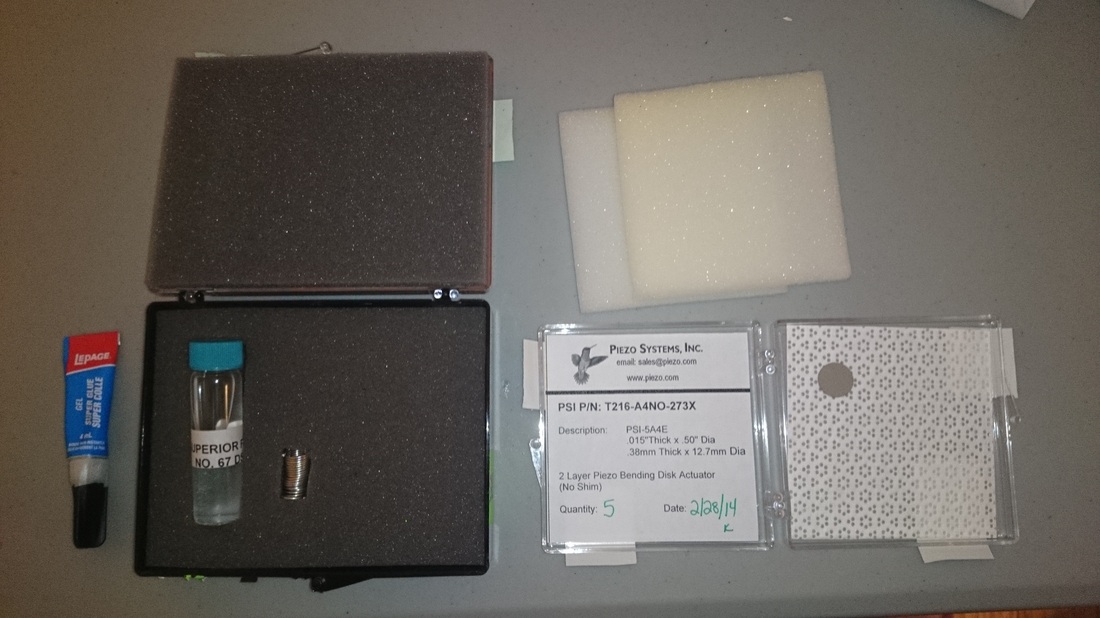
Piezoelectric elements requires special solder and flux. Soldering nickel electrodes is a different process than regular copper electrodes.
Thin gauge wires must be used in order to limit the strain on the solder joint. 32 AWG wire was used.
A soldering kit is available here.
Thin gauge wires must be used in order to limit the strain on the solder joint. 32 AWG wire was used.
A soldering kit is available here.
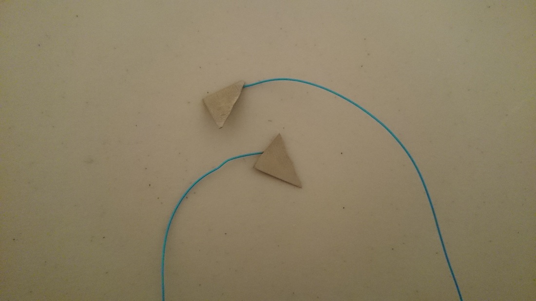
We found out the hard way that piezoelectric elements are very fragile. Fortunately, the broken piece shown in the picture was a "practice piece" included in the piezo soldering kit.
Once all the piezo elements are soldered, a strong adhesive is applied the wire near the solder joint in order to further reduce strain on the solder joint. The piezo discs are then glued down on their mechanical supports.
Original Electrical Design
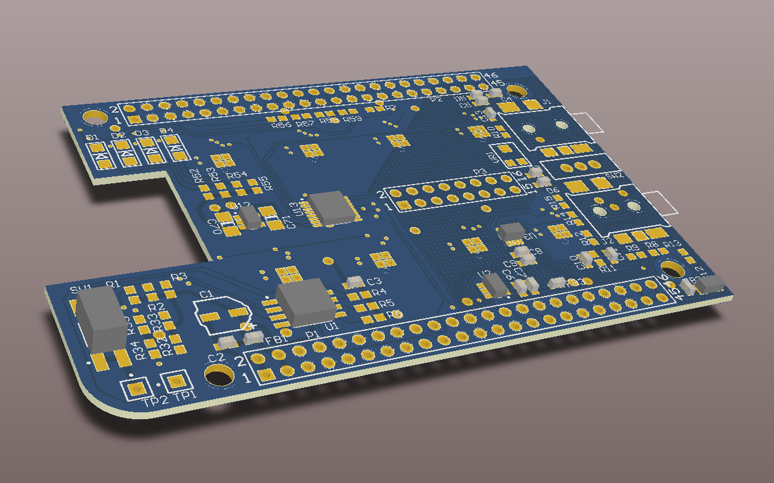
The picture to the left is a 3D view of the orginal VTSSHD expansion board.
It consists of:
- ADC: analog microphone input
- DACs: analog outputs for the piezo drivers
- Piezo drivers: drive piezo electric elements at high voltages
It consists of:
- ADC: analog microphone input
- DACs: analog outputs for the piezo drivers
- Piezo drivers: drive piezo electric elements at high voltages
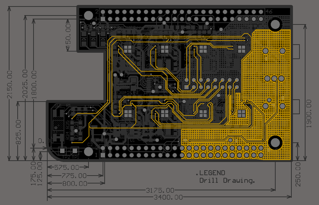
This picture is a 2D view of the VTSSHD expansion board, showing the dimensions (in mm).
